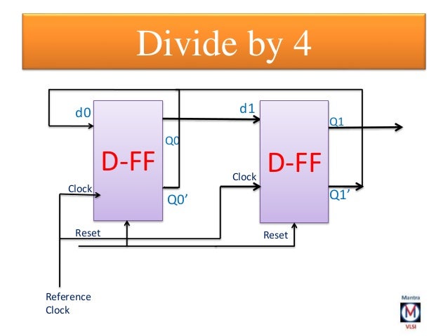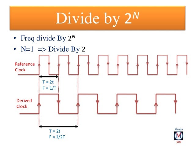


The simulation waveform also shows the frequency of clk_in is half of the clock frequency of clk_in. In the VHDL code for simulation purposes, the divisor is set to be 1 so the clock frequency of clk_out is obtained by dividing the frequency of clk_in by 2 as explained in the main VHDL code of the clock divider. VHDL Testbench code for clock divider on FPGA:

FPGA projects, VHDL projects, Verilog projects - VHDL project: VHDL code for digital clock on FPGA library IEEE Ĭlk_in : in std_logic - clock input on FPGAĪrchitecture Behavioral of clock_div is signal divisor : std_logic_vector( 27 downto 0) :=( others => '0') ĭivisor =x"2FAF07F") then - for running on FPGA - comment when running simulation - Modify the divisor (x"2FAF07F"=49999999) above to get the clock frequency you want: - Frequency of clk_out = Frequency of (clk_in) divided by (divisor + 1) - If the frequency of clk_in is 50MHz and the divisor is 49999999=x"2FAF07F", - the frequency of clk_out is 1Hz if(divisor >=x "0000001") then - for running simulation - comment when running on FPGA - divisor = 1 => divide clock by half for simulation purposesĮnd if if(divisor

 0 kommentar(er)
